Choosing an Ethernet PoE switch for a camera system usually starts with counting ports, and that is the least useful number on the datasheet. What stops a design is the wattage budget: the total power the switch can deliver across all its PoE ports at once. A 16-port switch with a modest budget will not run sixteen cameras that each want more than its share, and no amount of port counting changes that.
This article covers the three ranges we supply, how to size the budget from the devices you are actually connecting, what the IEEE 802.3af, 802.3at and 802.3bt standards do and do not tell you, and the two cable-distance rules that change the network design.
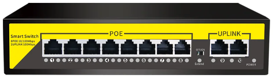
The range, briefly: the PS series comes as 8 PoE ports with two gigabit uplinks on a 120 W class budget, 16 ports on a 250 W class budget, and 24 ports on a 320 W class budget. Alongside them, the 24G02GS-P offers 24 full-gigabit ports with 2 SFP slots at 52 V, and the 1011GB provides 8 PoE ports with 2 uplinks and one SFP.
Why is the power budget the constraint, not the ports?
| Switch | PoE ports | Uplinks | Budget class | Typical use |
|---|---|---|---|---|
| PS082 | 8 | 2 × gigabit uplink | 120 W class | One floor, a small site, or a remote cabinet on a single uplink run |
| PS162 | 16 | Uplink to the core | 250 W class | A mid-size building or a floor with 12 to 14 active devices and a few spares |
| PS242 | 24 | Uplink to the core | 320 W class | A large floor or a central cabinet feeding several areas |
| 24G02GS-P | 24 | 2 × SFP | 52 V PoE | All-gigabit backbone switching with fibre uplinks |
| 1011GB | 8 | 2 × uplink + 1 × SFP | PoE | Small installations with a fibre uplink requirement |
How much margin does the arithmetic need?
Sizing the budget is one line of arithmetic, and the margin is not optional because a PoE switch running at its ceiling runs hot and has nothing left for the next camera:
Σ device power × 1.25 = the PoE budget to specify
Our cameras publish a power input of DC 12 V 2 A, so the ceiling to plan against is 24 W per camera at full specification, with the fill light, the warning light board and a 2 W speaker accounted for. Applied to the three PS models, that ceiling gives:
- 120 W class ÷ 1.25 ÷ 24 W = four cameras at the full ceiling
- 250 W class ÷ 1.25 ÷ 24 W = eight cameras at the full ceiling
- 320 W class ÷ 1.25 ÷ 24 W = ten cameras at the full ceiling
These numbers are deliberately pessimistic, and it is worth being explicit about why. The 12 V 2 A figure is the published rating of the camera’s power input, not a measured running draw: it assumes the fill light, the warning light board and the speaker are all at maximum simultaneously, which is not a normal operating state. The number to design against for a specific project is the measured draw of the model you are ordering, which we will confirm for you before the order is placed. What the ceiling does show is the shape of the problem: the budget usually runs out before the ports do, and it runs out faster than most bills of materials assume.
What do IEEE 802.3af, 802.3at and 802.3bt define?
Power over Ethernet is standardised by the IEEE 802.3 family: 802.3af introduced it for low-power devices, 802.3at raised the per-port envelope for devices such as pan-tilt-zoom cameras, and 802.3bt extended it further for higher-power equipment. The standards define how a powered device and a power sourcing port negotiate, and what each class may draw at the port.
Two consequences follow, and both matter at tender stage. First, a per-port class is not a total budget: a switch can report 30 W per port and 60 W total, which means two ports at full class and nothing for the rest. Second, the total budget is what the switch can deliver with every port active, so the specification line you need is the wattage, not the class. When you order, confirm which PoE classes the model you are buying supports, because a camera that negotiates a higher class than the port supports will either be refused or run degraded, and that is a commissioning problem rather than a design problem.
What changes at 100 m, with 250 m Extend and port isolation?
Standard PoE over network cable is limited to 100 m per run. It is a real limit and it decides cabinet positions, because a camera 130 m from the nearest switch is not a cable problem to be solved by a longer drum.
On the PS series there is a documented way past it: setting the VLAN DIP switch to the ON position enables 250 m Extend mode. Two things change at once. The link speed drops to 10 Mbps, and the ports become isolated from one another. Ten megabits is entirely adequate for a single camera stream, and port isolation is a security benefit in its own right — one compromised camera port cannot reach the rest of the switch. What it is not is a way to feed an uplink, a second switch or a wireless access point, all of which need the full link rate and a non-isolated path.
The 24G02GS-P handles this differently: its VLAN function is fixed at 0–100 m isolation, with no extend mode. Short runs behind the switch are isolated as a permanent configuration, which is the right choice for a cabinet intended for cameras only.
Why does the port count still matter?
Even when the budget is the binding constraint, the port count sets how a building is wired. Give every camera its own port, keep two or three spare ports on each switch for late additions, and treat the uplinks as a separate calculation. The 8-port PS082 comes with two gigabit uplinks, which allows a daisy-chained cabinet or a redundant path back to the core, depending on how your network is arranged. Where uplinks need to travel more than 100 m, or where electrical isolation between buildings is wanted, the SFP slots on the 24G02GS-P and the 1011GB are the reason to choose those models over the PS series.
One honest limit worth stating: these switches provide hardware-level functions — a VLAN DIP switch, port isolation and extend mode — rather than a software management plane. If your design requires SNMP monitoring, configurable 802.1Q VLANs or a full command-line interface, tell us before ordering, and we will confirm exactly what the model you are considering supports instead of letting a datasheet adjective decide it.
How do you size a CCTV PoE design?
- List every powered device: cameras, access points, intercoms. Note the form and the model.
- Get the measured or published draw for each, and use the published power input as the ceiling when no measurement exists.
- Sum the devices on each floor or area, multiply by 1.25, and that is the budget the switch for that area needs.
- Add two or three spare ports per switch, and choose the model above the budget you calculated rather than the one that exactly matches it.
- Check every run against the 100 m standard limit, and decide deliberately whether an extend-mode port or a closer cabinet is the better answer.
- Confirm the uplink route and whether SFP or a longer copper path is required.
Send us the device list and where it sits on the plan. We will come back with the switch models, the spare ports, the total wattage with margin, and a note on any run that will not make 100 m — including the honest cases where the answer is a second cabinet rather than a larger switch.