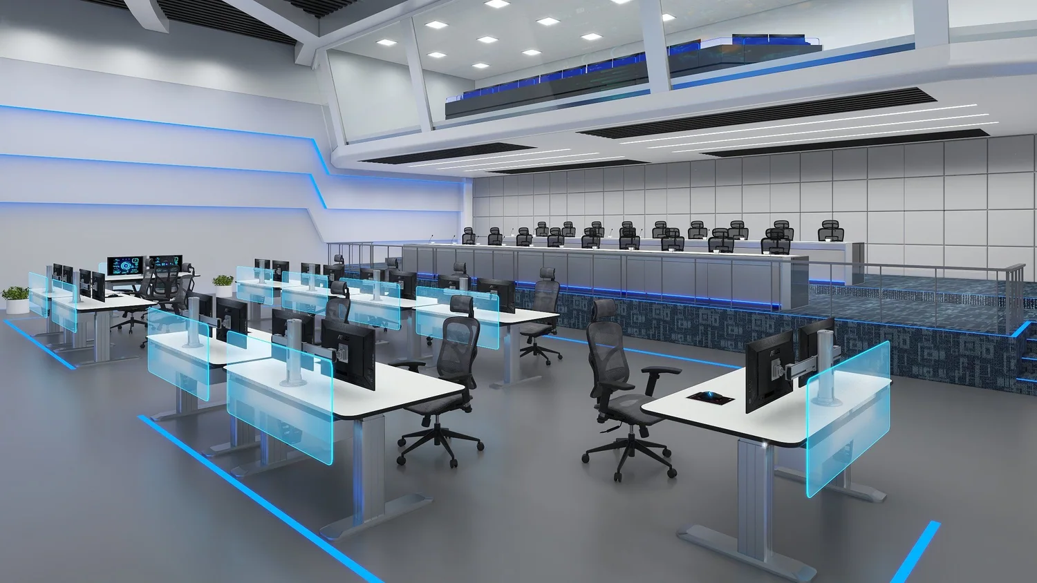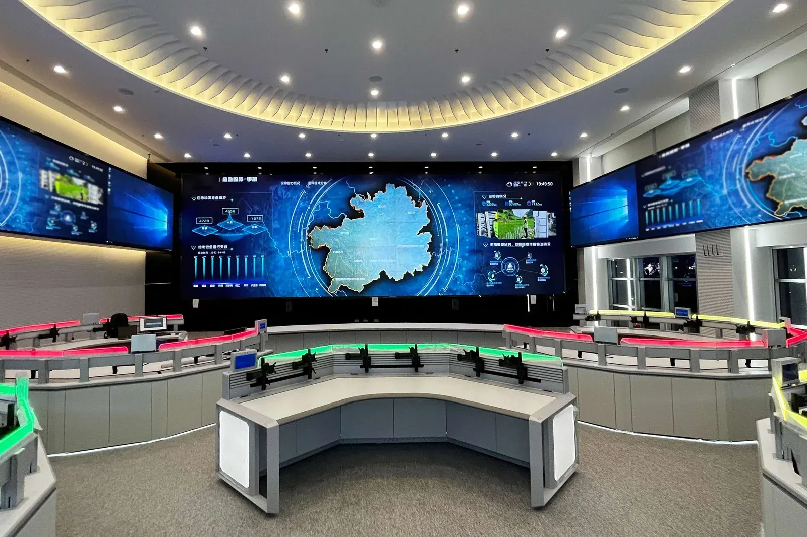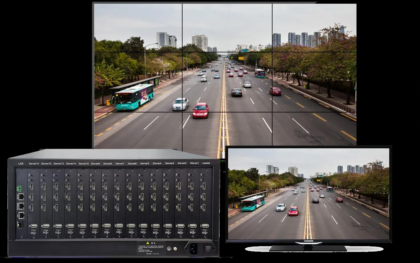
A control room video wall is usually specified from the room backwards — how much wall the space can take, how many panels fit — and that is the wrong end to start from. A video wall is a monitoring instrument, and it is sized by two numbers: how many camera streams have to be visible at the same time, and how large the single most important image needs to be when something happens. The panel count follows from those two answers, not from the available wall area.
This article works through the chain in the order it should be designed: streams first, then outputs and panels, then the decoder cards that make the layout possible, and finally the backplane and operator equipment that keep it running. The figures used are from our video wall range: a 14-slot modular chassis, 4K@60Hz decoding cards with two HDMI 2.0 outputs each, and a decode ladder that runs from one 3200 W stream down to 72 D1 streams on a single card.
Two terms to fix before the arithmetic. The layout describes the output side — a 2×2 wall is four panels, a 3×3 is nine, a 4×4 is sixteen. Decode capacity describes the input side. The two are matched by cards, and that matching is the whole design exercise.
Where do you start — what has to be watched at once?
Three questions decide the size of a monitoring wall, and all three are operational rather than technical.
- How many streams must be visible simultaneously in normal operation? Not how many cameras the site has — how many a single operator can keep in view at once, and how many the shift pattern requires.
- What is the largest single image that must be produced? If a serious incident requires one camera to be shown across a large area of the wall for a supervisor or a visiting police officer, that requirement sets the minimum panel size and the resolution of the panels themselves.
- How many people use the wall, and for what? One guard watching a building at night and three operators running a campus are different designs, even when the building sizes are similar.
Write the answers down before choosing a layout. A 2×2 wall that shows four large images and a 3×3 wall showing nine moderate ones solve different problems, and neither is a downgrade from the other.
How do outputs, cards and panel count relate?
Each decoding card provides two HDMI 2.0 outputs capable of 4K at 60 Hz, plus one HDMI input and one audio input and output. Each output drives one panel, so the number of panels sets the number of cards:
| Layout | Panels | HDMI outputs needed | Cards needed | Slots left in the 14-slot chassis |
|---|---|---|---|---|
| 2×2 | 4 | 4 | 2 | 12 |
| 3×3 | 9 | 9 | 5 | 9 |
| 4×4 | 16 | 16 | 8 | 6 |
Two things are worth noting from that table. First, an odd panel count such as 3×3 uses five cards, which leaves one unused output — useful for a preview screen at the operator desk, and a good reason not to treat the arithmetic as a defect. Second, the modular chassis has capacity well beyond a 4×4 wall: a 4×4 uses eight of fourteen slots, leaving room for expansion or for a mixed input card later.
How many cameras can each layout actually show?
Decode capacity is published per card, and it is the number that decides whether the wall can actually display the cameras on the drawing. One card decodes one 3200 W stream, two 1200 W or 4K streams, eight 500 W streams, 24 streams at 1080p, 32 at 720p or 72 at D1 — not simultaneously at every tier, but as the ladder you choose from.
Multiply by the card count and the layouts scale like this:
- 2×2 on two cards: up to 48 streams at 1080p in mosaic, or 4 at 4K/1200 W, or 16 at 500 W.
- 3×3 on five cards: up to 120 streams at 1080p in mosaic, or 10 at 4K/1200 W, or 40 at 500 W.
- 4×4 on eight cards: up to 192 streams at 1080p in mosaic, or 16 at 4K/1200 W, or 64 at 500 W.
A single card also supports 36-way splitting, and two 36-way splits can run on one card at the same time, with up to 72 IP cameras on the wall from that card. These are mosaic figures: they describe many streams shown small, which is exactly what a control room wall does most of the time. If your design puts one camera across several panels, or mixes large and small images in a specific arrangement, tell us the intended layout and we will confirm the card configuration rather than leaving it to a spreadsheet.
What does the wall accept, and in which codec?
The decoding server accepts camera streams over GB28181, ONVIF, RTSP and DDNS, which means it will take feeds from our own cameras and from other ONVIF-compliant equipment on the same network. Beyond IP streams, it also accepts analogue signal from AHD, CVI and TVI cameras through encoders, HDMI and VGA signals from workstations, and network set-top boxes.
On the codec side, the platform decodes H.265+ at Main Profile Level 5.1, H.264 at Baseline, Main and High Profile Level 5.0, MPEG4 and MJPEG. That list matters more than it looks: H.265+ at Level 5.1 is what makes 4K streams practical to bring in at volume, and it is the same compression our cameras use on the main stream, so a 5 MP channel arriving at the wall carries the same bitrate benefit it had on the recorder. Each output runs at up to 4K at 60 Hz, so specify panels to match: 1080p panels behind a 4K output waste the output, and 4K panels behind a 1080p source achieve nothing.
Which operating features decide day-to-day usefulness?
Two features separate a wall that is used from a wall that is looked at occasionally.
The first is labelling. The platform supports OSD region name overlay and IP channel characters on the wall, so an operator sees which camera a window belongs to rather than a number that has to be looked up. On a 4×4 wall with dozens of windows, that is the difference between a monitoring tool and a decoration.
The second is fault visibility. The controller supports real-time line disconnection detection, so a camera that has failed or a link that has dropped shows up on the wall itself rather than in a log nobody reads. On any site where the wall is the primary way the building is watched, that is a security function, not a convenience.
Behind both sits the architecture: the chassis uses a dual 24-port full-gigabit switching backplane with a 96 Gbps backplane bandwidth and a 72 Mpps forwarding rate, and the decode streams from cameras are physically isolated from the splicing image streams. That separation is why a wall full of mosaic windows does not compete with the wall’s own internal image traffic.
How do you choose between 2×2, 3×3 and 4×4?
- 2×2 — four panels. A guard room or a small control room with one operator. Best when the job is to see a few large images well: entrances, a gate, a perimeter, plus one window for an incident. With 4K panels it produces a genuinely large single image, which is the requirement that most often drives a small wall.
- 3×3 — nine panels. A building control room with two or three operators, where the requirement is a spread of areas visible at once plus room for a large incident view. The natural fit for a site with a few hundred cameras and a shift-based team.
- 4×4 — sixteen panels. A campus or command environment where the wall must carry many streams, several large views and dedicated positions for specific systems at the same time. It uses eight cards, so plan the chassis, the power and the rack space together rather than adding panels later.
The operator desk is part of the same decision. The network PTZ control keyboard YK-41DP runs Linux, supports up to 999 devices, uses a 4D joystick, works over ONVIF and drives a single channel at up to 1080p and 30 fps. Its TFT LCD panel is 800 × 480, it runs from DC 12 V 2 A at 5 W or less, and it operates between -10 °C and +55 °C at a weight of 900 g. If the wall is the output, the keyboard is how the operators actually use it during an incident.
Send us the stream count you need visible at once, the largest single image requirement and the number of operators, and we will return the layout, the panel count, the card configuration and the chassis slots it uses. If the honest answer is that a 2×2 wall meets the requirement, we will quote that rather than a larger wall the room could take.